How Do Liquid Cooling Rapid Chargers Work?
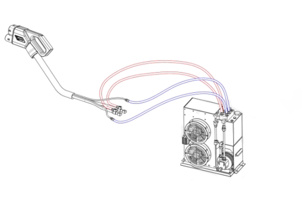
Liquid cooling rapid chargers use liquid-cooled cables to help combat the high levels of heat associated with high charging speeds. The cooling takes place in the connector itself, sending coolant flowing through the cable and into the contact between the car and the connector. Because the cooling takes place inside the connector, the heat dissipates almost instantly as the coolant travels back and forth between the cooling unit and the connector. Water-based liquid cooling systems can dissipate heat up to 10 times more efficiently, and other liquids can further improve cooling efficiency. Therefore, liquid cooling is receiving more and more attention as the most efficient solution available.
Liquid cooling allows the charging cables to be thinner and lighter, reducing the cable weight by around 40%. This makes them easier for the average consumer to use when charging their vehicle.
Liquid cooling fluid connectors are designed to be durable and withstand external conditions such as high levels of heat, cold, moisture and dust. They’re also designed to withstand massive amounts of pressure to avoid leaks and sustain themselves throughout long charging times.
The liquid cooling process for electric vehicle chargers typically involves a closed-loop system. The charger is equipped with a heat exchanger that is connected to a cooling system, which can be either air-cooled or liquid-cooled. The heat generated during charging is transferred to the heat exchanger, which then transfers it to the coolant. The coolant is typically a mixture of water and a coolant additive, such as glycol or ethylene glycol. The coolant circulates through the charger’s cooling system, absorbing heat and transferring it to a radiator or heat exchanger. The heat is then dissipated into the air or transferred to a liquid cooling system, depending on the design of the charger.

With liquid cooling for the contacts and the high-performing coolant , the power rating can be boosted up to 500 kW (500 A at 1000V) that can deliver a 60-mile range charge in as little as three to five minutes.

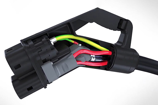
The interior of a high-power CSS connector shows the AC cables (green) and liquid cooling for the DC cables (red).
Charging Cable Parameter


